DMVPN has always been one of my favorite networking technologies. One of the first networks I ever touched was a phase 1 DMVPN. I quickly realized some of the benefits it can bring. This will not be a comprehensive article covering all things DMVPN. Today I just want to cover the basics of spoke-to-spoke tunnel control plane for DMVPN phase 3. I’ll touch briefly on phase 1 and phase 2.
Demo Network
I don’t have a CML topology to share this time; this network was built on real gear. It’s a simple 3 router network with IP connectivity between them. The transport (aka NBMA, Non-Broadcast Multiaccess) and tunnel IP addresses are shown on the diagram.
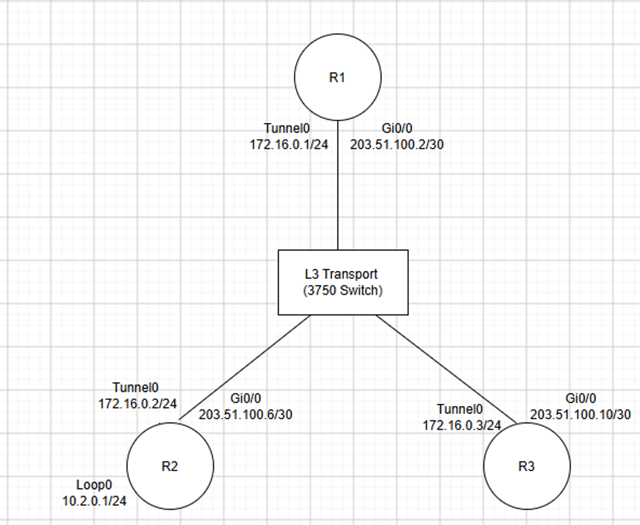
DMVPN High Level
The magic of DMVPN is that hub and spoke overlay networks can be built with just a single tunnel interface on the hub. The tunnel runs in GRE multipoint mode. DMVPN phase 1 uses this technique to build hub and spoke overlay connectivity. DMVPN phase 2 deploys multipoint GRE on the spokes also and allows the spokes to build spoke-to-spoke tunnels on demand. Phase 2 requires that the hub reflect routes from spoke-to-spoke without changing the next hop. If our demo network were phase 2, R3 would have a route to 10.2.0.0/24 via 172.16.0.2. If R3 wanted to build a tunnel to R2, it would have to use NHRP (Next Hop Resolution Protocol) to query the hub to figure out the transport (aka NMBA, 203.51.100.6 in our example) to build a tunnel.
There are drawbacks to phase 2 and the requirement to preserve the route’s next hop (the hub cannot set itself as the next hop when advertising spoke routes to other spokes). The hub cannot aggregate routes because that would cause the hub to be the next hop of the aggregate route.
DMVPN phase 3 solves this problem. With phase 3, spoke to spoke routes use the hub as the next hop. When traffic “hairpins” though the hub’s tunnel interface, it will notice and send an NHRP traffic indication packet to the source spoke. This triggers the source spoke to send an NHRP resolution request to the hub. The resolution request is asking what destination IP address should be used to build a tunnel directly to the destination spoke. The hub does something you might not expect. It forwards the resolution request to the destination spoke. The destination spoke will reply directly to the source spoke with the requested information. This guarantees that the answer is authoritative. The destination spoke tells the source spoke what its IP address is.
Redirects
I said a lot and this can be hard to imagine so let’s look at some traffic! As we expect for phase 3, R3 has a route to R2’s loopback with R1 (the hub) as the next hop.
RoutingLoop_R3#show ip route 10.2.0.1
Routing entry for 10.2.0.0/24
  Known via "eigrp 1", distance 90, metric 102400640, type internal
  Redistributing via eigrp 1
  Last update from 172.16.0.1 on Tunnel0, 02:16:41 ago
  Routing Descriptor Blocks:
  * 172.16.0.1, from 172.16.0.1, 02:16:41 ago, via Tunnel0
      Route metric is 102400640, traffic share count is 1
      Total delay is 100002 microseconds, minimum bandwidth is 100 Kbit
      Reliability 255/255, minimum MTU 1400 bytes
      Loading 1/255, Hops 2
An initial traceroute from R3 to the R2 loopback goes to the hub and then down to R2. This makes sense for what the routing tables says, but I thought phase 3 did dynamic spoke to spoke connectivity?! It did, we just didn’t see it in this initial traceroute.
RoutingLoop_R3#traceroute 10.2.0.1
Type escape sequence to abort.
Tracing the route to 10.2.0.1
VRF info: (vrf in name/id, vrf out name/id)
  1 172.16.0.1 4 msec 0 msec 0 msec
  2 172.16.0.2 0 msec *  0 msec
Running the traceroute a 2nd time show R2 as the first hop. The first traceroute triggered the dynamic spoke-to-spoke tunnel to be formed.
RoutingLoop_R3#traceroute 10.2.0.1
Type escape sequence to abort.
Tracing the route to 10.2.0.1
VRF info: (vrf in name/id, vrf out name/id)
  1 172.16.0.2 4 msec *  0 msec
Let’s look at the control plane traffic that makes this happen. The example packets were triggered by a ping from R3 to R2’s loopback.
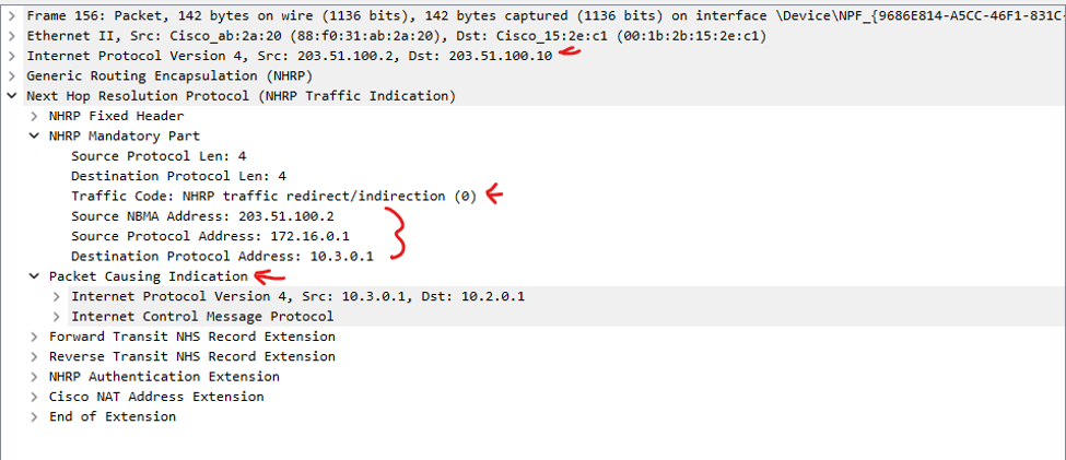
The first interesting packet is the traffic indication from the hub going to R3. This is a hint for R3 to recognize that it may not be using the best path to reach 10.2.0.1. This is the hub’s way of saying “Hey buddy, I told you that I am the next hop for 10.2.0.0/24 but maybe I fibbed a bit”. The traffic indication contains a portion of the packet that caused the indication to be sent.
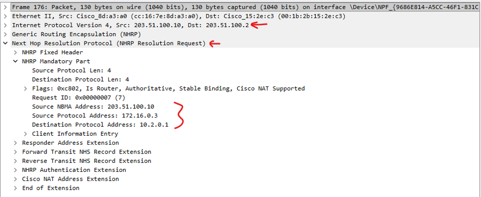
R3 receives this hint from the hub and sends an NHRP Resolution Request. This is R3 saying to the hub “Ok, thanks for the hint. Please provide the NBMA address of the destination spoke for 10.2.0.1 so I can build a direct tunnel.”
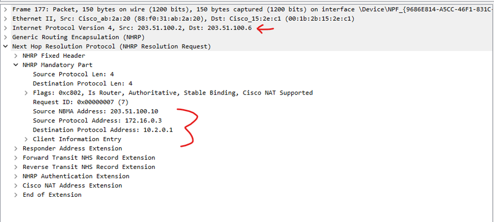
This next packet may look partially familiar. The hub forwarded R3’s resolution request down to R2, the spoke where 10.2.0.1 lives. This is the NHRP function that many engineers do not expect. The hub must have an NHRP entry for R2 if it has a tunnel to it. Instead of the hub replying, it sends the request downstream to allow the destination spoke to reply.
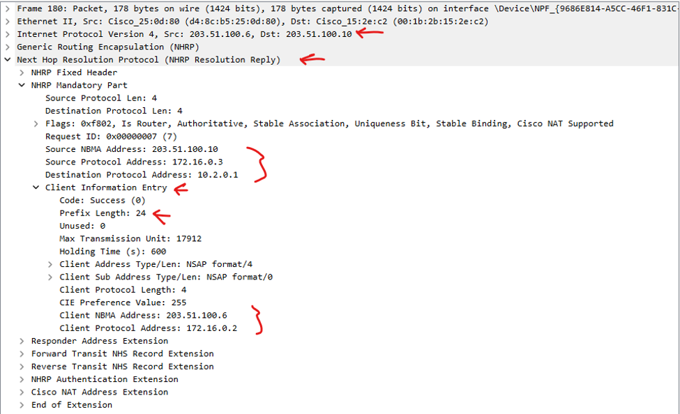
R2 then sends an NHRP Resolution Reply directly to R3. This reply contains some important information. The destination protocol address is the IP on R2 we are trying to reach; the subnet mask of this network is also sent so that any future packets to other hosts in the subnet can go direct. The Client Information Entry field tells R3 what the VPN IP (172.16.0.2) and NBMA (203.51.100.6) IP addresses are. This is the most critical glue that allows R3 to build a tunnel directly to R2, bypassing the hub.
Verification Commands
We can use the ‘show ip nhrp detail’ command on R3 to see the NHRP cache entry for 10.2.0.0. Notice that these entries to not last forever, there is a timeout to flush old NHRP cache entries. This output shows us what we saw in the pcap. To reach 10.2.0.0/24, we need to use tunnel0 with next hop 172.16.0.2. We need to build this tunnel to NBMA address 203.51.100.6. This is the Gi0/0 IP of R2.
RoutingLoop_R3#show ip nhrp 10.2.0.0 detail
10.2.0.0/24 via 172.16.0.2
   Tunnel0 created 00:02:01, expire 00:07:58
   Type: dynamic, Flags: router rib nho
   NBMA address: 203.51.100.6
   Preference: 255
Show ip cef displays the forwarding table entry.
RoutingLoop_R3#show ip cef 10.2.0.1
10.2.0.0/24
  nexthop 172.16.0.2 Tunnel0
Show dmvpn is one of the best commands for DMVPN networks. This output shows us two entries for our dynamic tunnel to R2 and one to our static tunnel to the hub.
RoutingLoop_R3#show dmvpn
Legend: Attrb --> S - Static, D - Dynamic, I - Incomplete
        N - NATed, L - Local, X - No Socket
        T1 - Route Installed, T2 - Nexthop-override
        C - CTS Capable, I2 - Temporary
        # Ent --> Number of NHRP entries with same NBMA peer
        NHS Status: E --> Expecting Replies, R --> Responding, W --> Waiting
        UpDn Time --> Up or Down Time for a Tunnel
==========================================================================

Interface: Tunnel0, IPv4 NHRP Details
Type:Spoke, NHRP Peers:2,

 # Ent  Peer NBMA Addr Peer Tunnel Add State  UpDn Tm Attrb
 ----- --------------- --------------- ----- -------- -----
     2 203.51.100.6         172.16.0.2    UP 00:02:10   DT2
                            172.16.0.2    UP 00:02:10   DT1
     1 203.51.100.2         172.16.0.1    UP 03:15:13     S
DT1 means “dynamic and route installed”. DT2 means “dynamic and next-hop override”. Next hop override means NHRP changed the next hop from what we had in the routing table (R1) to be R2s tunnel IP instead. The command below shows the route with NHO, next hop override.
RoutingLoop_R3#show ip route next-hop-override 10.2.0.0
Routing entry for 10.2.0.0/24
  Known via "eigrp 1", distance 90, metric 102400640, type internal
  Redistributing via eigrp 1
  Last update from 172.16.0.1 on Tunnel0, 03:23:10 ago
  Routing Descriptor Blocks:
  * 172.16.0.1, from 172.16.0.1, 03:23:10 ago, via Tunnel0
      Route metric is 102400640, traffic share count is 1
      Total delay is 100002 microseconds, minimum bandwidth is 100 Kbit
      Reliability 255/255, minimum MTU 1400 bytes
      Loading 1/255, Hops 2
    [NHO]172.16.0.2, from 172.16.0.2, 00:06:41 ago, via Tunnel0
      Route metric is 255, traffic share count is 1
      Total delay is 0 microseconds, minimum bandwidth is 1 Kbit
      Reliability 0/255, minimum MTU 0 bytes
      Loading 0/255, Hops 0
      Route tag 1
RoutingLoop_R3#
I’ll attempt to draw on the diagram step by step to show the process.
- R3 sends a ping to R2’s loopback.
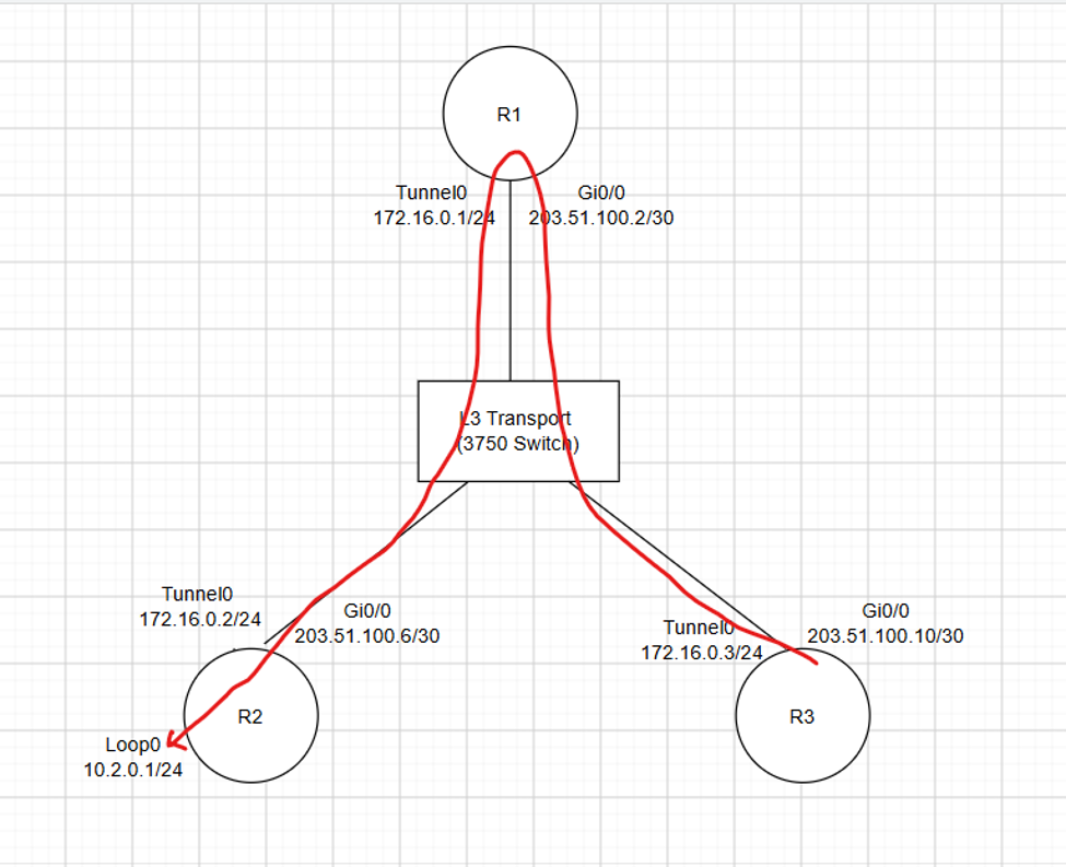
2. R1 notices the traffic hair pinning on Tunnel0 and sends an NHRP traffic indication to R3. This is to notify R3 that it should request an NHRP redirect.
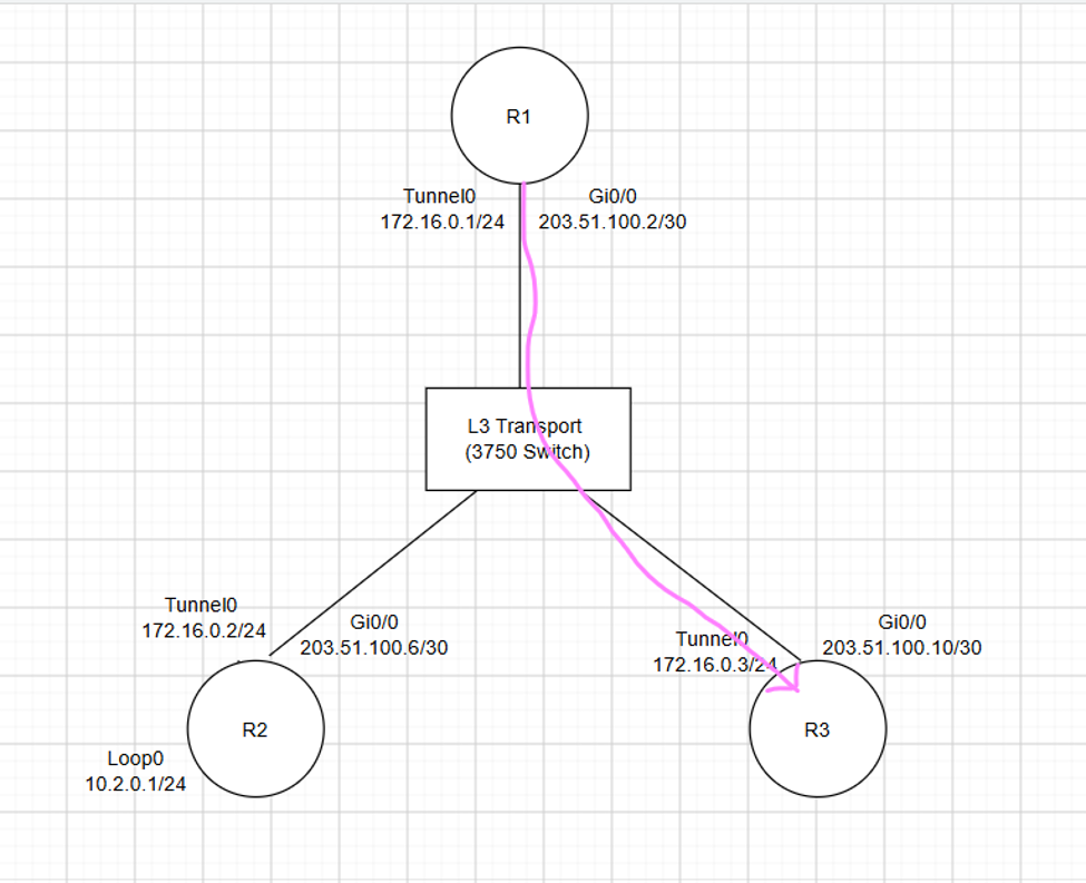
3. R3 sends an NHRP resolution request to the next hop server, aka the hub.
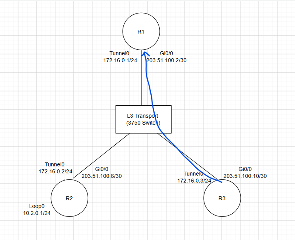
4. R1 forwards the NHRP resolution request to the destination spoke, R2.
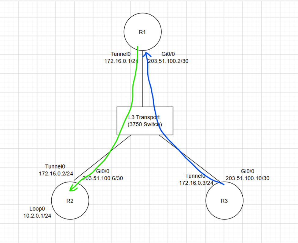
5. R2 responds directly to R3 with the tunnel and NBMA IPs that R3 needs to build a tunnel directly to R2.
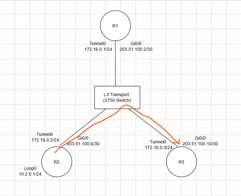
6. R3 establishes a tunnel directly to R2.
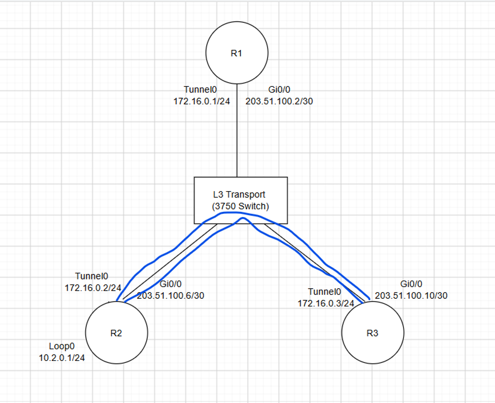
I haven’t mentioned it out but the return traffic from R2 (ICMP echo reply) triggers this process in the reverse direction so that R2 establishes a tunnel directly to R3. This allows bidirectional communication between R2 and R3 directly.
That’s all for now! If you made it this far, thanks for sticking with me!