Routingloop.net finally lives up to its name! In this article, I touch on how microloops happen and display how I was able to create and observe a live microloop.
What is a microloop anyways? A microloop is a temporary forwarding loop that can occur during network convergence, typically with link state protocols. Why link state? Link state protocols rely on all routers (or intermediate systems) within an area/flooding domain to have consistent Link State Databases (LSDBs) for all routers to make consistent forwarding decisions. During convergence, we can have inconsistent LSDBs, but there is more to it than that. Even after the LSDBs are synchronized, each router must run the Shortest Path First (SPF) algorithm and publish the results of the SPF run to the RIB, which is pushed to the FIB. Microloops can occur when a topology change occurs and one router converges to the new topology before other routers do.
Consider the topology below. The SPAN switch is only an ethernet bridge to copy packets for Wireshark. All routers are running IS-IS with default link cost. For the Raspberry Pi to reach R2’s loopback, traffic will flow from Pi > T > R1 > R2, the return path is the opposite.

If the link between R1 and R2 were to fail, the network will have to go through a multi-step convergence process.
Step 1. Detect the failure. This could be loss of carrier signal on the link, BFD, or routing protocol hello timers.
Step 2. Flood the news. R1 and R2 will send Link State Protocol Data Units (LSPs) informing the rest of the flooding domain about the change. We will look at these packets later.
Step 3. Run Dijkstra’s SPF algorithm to calculate the new shortest path tree.
Step 4. Install forwarding information for the new topology in the RIB and FIB.
When the R1 – R2 link fails (aka I unplug the cable), both routers detect this by loss of carrier signal on the link. This loss of carrier is published to the RIB to remove any next hops reachable via this link. The RIB informs IS-IS of this change. R1 will flood an LSP that does not list R2 as its neighbor and also does not include link subnet 172.19.0.0/30. R2 does the same by removing R1 as its neighbor and removing the subnet. This will be flooded to all other routers. Because R1 and R2 are the first to know about the change, they run SPF first. R1 will select T as the next hop to reach 10.0.0.1.
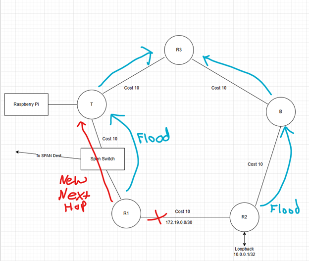
The loop occurs when R1 flips over to using T as the next hop, but T has not yet converged and is still using R1 as the next hop. Packets loop between T and R1 until T converges and installs next hop R3 to reach 10.0.0.1.

The Time to Live (TTL) of the looping packets is decremented at each router. What does this mean for the network and the applications that rely on it? If the loop is resolved and the packets have enough TTL to reach the destination, the loop manifests as jitter. If normal round-trip time between endpoints is 25 milliseconds and the microloop lasts 75 milliseconds, the end-to-end delay is 100 milliseconds during the microloop. Longer lived loops could be noticeable to near real time applications such as voice and video. Worse outcomes could be that the link is overwhelmed with traffic during the loop, causing packet loss. Packets that make it through the congestion could be subject to increased delay if the routers have deep buffers. Another possibility is that the loop is long lived enough for TTL expiration.
I created the topology shown using physical equipment in my home lab. On T, I set the IS-IS SPF interval to 120 seconds to make the microloop last long enough for TTL to expire so the loop is easy to spot. Config below.
router isis
 net 49.0000.0000.0000.0004.00
 is-type level-1
 spf-interval 120
The SPF interval specifies the minimum time between SPF runs. I started the lab demo with the R1-R2 link disconnected. I started a ping from the Pi to R2’s loopback. The ping request and reply are taking the only possible path, the path though R3 > B > R2. This path causes the ping replies to have TTL 252 when the Pi receives them.
pi@routerberrypi:~ $ ping 10.0.0.1 -t 16
PING 10.0.0.1 (10.0.0.1) 56(84) bytes of data.
64 bytes from 10.0.0.1: icmp_seq=1 ttl=252 time=0.872 ms
64 bytes from 10.0.0.1: icmp_seq=2 ttl=252 time=0.699 ms
64 bytes from 10.0.0.1: icmp_seq=3 ttl=252 time=0.719 ms
64 bytes from 10.0.0.1: icmp_seq=4 ttl=252 time=0.688 ms
64 bytes from 10.0.0.1: icmp_seq=5 ttl=252 time=0.784 ms
~ lines omitted for brevity ~
I then connected the R1-R2 cable, triggering SPF run #1. I can tell when the network converges to the new topology when the ping replies TTLs increase to 253.
64 bytes from 10.0.0.1: icmp_seq=56 ttl=252 time=0.705 ms
64 bytes from 10.0.0.1: icmp_seq=57 ttl=252 time=0.753 ms
64 bytes from 10.0.0.1: icmp_seq=58 ttl=253 time=0.706 ms
64 bytes from 10.0.0.1: icmp_seq=59 ttl=253 time=0.727 ms
64 bytes from 10.0.0.1: icmp_seq=60 ttl=253 time=0.648 ms
Once I see TTL 253 replies, I disconnected the cable between R1-R2. Ping packets 61-68 are lost while R1 converges. Router T tries to initiate SPF run #2 but it must wait for the increased SPF interval to expire before it can calculate the new topology. As soon as R1 flips over to using T as its next hop, we have a microloop while the SPF interval timer is counting down on T.
The microloop is evident by the ICMP time to live exceeded messages received by the Pi.
64 bytes from 10.0.0.1: icmp_seq=59 ttl=253 time=0.727 ms
64 bytes from 10.0.0.1: icmp_seq=60 ttl=253 time=0.648 ms
From 172.20.0.1 icmp_seq=69 Time to live exceeded
From 172.20.0.1 icmp_seq=70 Time to live exceeded
From 172.20.0.1 icmp_seq=71 Time to live exceeded
From 172.20.0.1 icmp_seq=72 Time to live exceeded
From 172.20.0.1 icmp_seq=73 Time to live exceeded
From 172.20.0.1 icmp_seq=74 Time to live exceeded
From 172.20.0.1 icmp_seq=75 Time to live exceeded
From 172.20.0.1 icmp_seq=76 Time to live exceeded
From 172.20.0.1 icmp_seq=77 Time to live exceeded
From 172.20.0.1 icmp_seq=78 Time to live exceeded
From 172.20.0.1 icmp_seq=79 Time to live exceeded
64 bytes from 10.0.0.1: icmp_seq=80 ttl=252 time=0.798 ms
64 bytes from 10.0.0.1: icmp_seq=81 ttl=252 time=0.760 ms
The ICMP echo request ping-pong between R1 and T until T is finally able to run SPF and install the new next hop via R3. We can see the reply TTL drop to 252 after convergence.
Packet Captures:
Earlier I mentioned that I triggered back-to-back SPF runs by first connecting the R1-R2 cable and disconnected it again. In this section, we’ll look at some of the relevant packets.
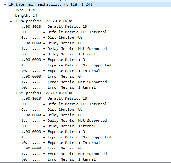
When the R1-R2 cable was first connected, R1 sent an LSP to T informing the flooding domain of the new neighborship with R2, and the subnet of the R1-R2 link, shown below. R2 floods a similar LSP to inform the network about its new neighbor and IP network.

The LSP IS Reachability section shows R1 (LSP-ID 0000.0000.0001) is neighbors with IS ~0004 (aka T), and ~ 0002, aka R2. This lets everyone know that IS R1 and R2 are connected to each other. This information is required for building the shortest path tree.
The IP Internal Reachability section of the LSP shows that R1 is connected to networks 172.19.0.0/30 and 172.20.0.0/30. All routers in the area will run SPF. Router T will begin R1 as its next hop to reach R2’s loopback.
As stated earlier, I disconnected the cable after convergence to initiate the microloop. When R1 detects that the link to R2 is down, an IS-IS LSP is flooded to remove this link from the topology, shown below.
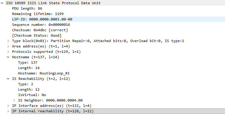
Only Router T’s ID is listed as a neighbor of R1, this informs the network that the link to R2 is no longer present.
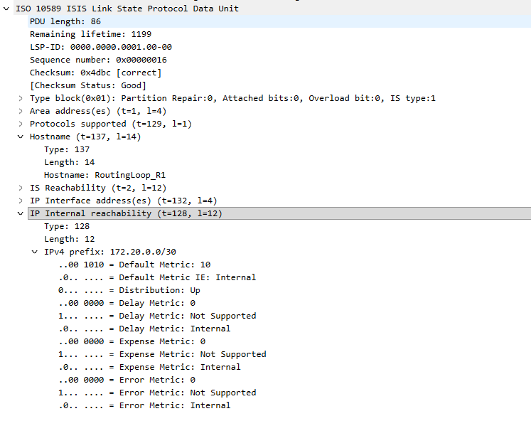
The IP Reachability section no longer includes the subnet of the R1-R2 link, 172.19.0.0/30. Only the subnet for the R1-T link is included in this new LSP.
R1 quickly converges to the new topology but remember that T has a long SPF interval and SPF run #1 occurred when the R1-R2 link established. T must wait until the SPF interval timer expires to find the new shortest path tree. We can see the results of this in the Wireshark capture shown below.
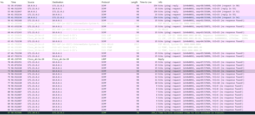
Toward the top we see ping request and replies. When the link is disconnected, the ping replies stop and IS-IS LSPs are flooded. Packet 73 is an indicator that R1 has converged around the failure and started using T as the next hop for 10.0.0.1. The TTL of the ping request counts down from packet 72 to 86. This is the same ICMP echo request looping between R1 and T until the TTL eventually expires and an ICMP Time to Live exceeded message is sent to the Raspberry Pi. I used reduced TTL on the echo request so that TTL countdown and TTL exceed packets would all fit on one screen. The full ping output from the Pi is shown below. Notice the TTL of the reply packets change as the network path changes and the TTL exceeded messages during the loop.
pi@routerberrypi:~ $ ping 10.0.0.1 -t 16
PING 10.0.0.1 (10.0.0.1) 56(84) bytes of data.
64 bytes from 10.0.0.1: icmp_seq=1 ttl=252 time=0.872 ms
64 bytes from 10.0.0.1: icmp_seq=2 ttl=252 time=0.699 ms
64 bytes from 10.0.0.1: icmp_seq=3 ttl=252 time=0.719 ms
64 bytes from 10.0.0.1: icmp_seq=4 ttl=252 time=0.688 ms
64 bytes from 10.0.0.1: icmp_seq=5 ttl=252 time=0.784 ms
64 bytes from 10.0.0.1: icmp_seq=6 ttl=252 time=0.775 ms
64 bytes from 10.0.0.1: icmp_seq=7 ttl=252 time=0.730 ms
64 bytes from 10.0.0.1: icmp_seq=8 ttl=252 time=0.698 ms
64 bytes from 10.0.0.1: icmp_seq=9 ttl=252 time=0.709 ms
64 bytes from 10.0.0.1: icmp_seq=10 ttl=252 time=0.692 ms
64 bytes from 10.0.0.1: icmp_seq=11 ttl=252 time=0.778 ms
64 bytes from 10.0.0.1: icmp_seq=12 ttl=252 time=0.687 ms
64 bytes from 10.0.0.1: icmp_seq=13 ttl=252 time=0.725 ms
64 bytes from 10.0.0.1: icmp_seq=14 ttl=252 time=0.727 ms
64 bytes from 10.0.0.1: icmp_seq=15 ttl=252 time=0.717 ms
64 bytes from 10.0.0.1: icmp_seq=16 ttl=252 time=0.770 ms
64 bytes from 10.0.0.1: icmp_seq=17 ttl=252 time=0.757 ms
64 bytes from 10.0.0.1: icmp_seq=18 ttl=252 time=0.729 ms
64 bytes from 10.0.0.1: icmp_seq=19 ttl=252 time=0.744 ms
64 bytes from 10.0.0.1: icmp_seq=20 ttl=252 time=0.710 ms
64 bytes from 10.0.0.1: icmp_seq=21 ttl=252 time=0.741 ms
64 bytes from 10.0.0.1: icmp_seq=22 ttl=253 time=0.729 ms
64 bytes from 10.0.0.1: icmp_seq=23 ttl=253 time=0.727 ms
64 bytes from 10.0.0.1: icmp_seq=24 ttl=253 time=0.705 ms
64 bytes from 10.0.0.1: icmp_seq=25 ttl=253 time=0.676 ms
64 bytes from 10.0.0.1: icmp_seq=26 ttl=253 time=0.716 ms
64 bytes from 10.0.0.1: icmp_seq=36 ttl=252 time=0.813 ms
64 bytes from 10.0.0.1: icmp_seq=37 ttl=252 time=0.712 ms
64 bytes from 10.0.0.1: icmp_seq=38 ttl=252 time=0.780 ms
64 bytes from 10.0.0.1: icmp_seq=39 ttl=252 time=0.703 ms
64 bytes from 10.0.0.1: icmp_seq=40 ttl=252 time=0.775 ms
64 bytes from 10.0.0.1: icmp_seq=41 ttl=252 time=0.706 ms
64 bytes from 10.0.0.1: icmp_seq=42 ttl=252 time=0.681 ms
64 bytes from 10.0.0.1: icmp_seq=43 ttl=252 time=0.716 ms
64 bytes from 10.0.0.1: icmp_seq=44 ttl=252 time=0.796 ms
64 bytes from 10.0.0.1: icmp_seq=45 ttl=252 time=0.792 ms
64 bytes from 10.0.0.1: icmp_seq=46 ttl=252 time=0.712 ms
64 bytes from 10.0.0.1: icmp_seq=47 ttl=252 time=0.708 ms
64 bytes from 10.0.0.1: icmp_seq=48 ttl=252 time=0.728 ms
64 bytes from 10.0.0.1: icmp_seq=49 ttl=252 time=0.734 ms
64 bytes from 10.0.0.1: icmp_seq=50 ttl=252 time=0.761 ms
64 bytes from 10.0.0.1: icmp_seq=51 ttl=252 time=0.740 ms
64 bytes from 10.0.0.1: icmp_seq=52 ttl=252 time=0.730 ms
64 bytes from 10.0.0.1: icmp_seq=53 ttl=252 time=0.732 ms
64 bytes from 10.0.0.1: icmp_seq=54 ttl=252 time=0.767 ms
64 bytes from 10.0.0.1: icmp_seq=55 ttl=252 time=0.711 ms
64 bytes from 10.0.0.1: icmp_seq=56 ttl=252 time=0.705 ms
64 bytes from 10.0.0.1: icmp_seq=57 ttl=252 time=0.753 ms
64 bytes from 10.0.0.1: icmp_seq=58 ttl=253 time=0.706 ms
64 bytes from 10.0.0.1: icmp_seq=59 ttl=253 time=0.727 ms
64 bytes from 10.0.0.1: icmp_seq=60 ttl=253 time=0.648 ms
From 172.20.0.1 icmp_seq=69 Time to live exceeded
From 172.20.0.1 icmp_seq=70 Time to live exceeded
From 172.20.0.1 icmp_seq=71 Time to live exceeded
From 172.20.0.1 icmp_seq=72 Time to live exceeded
From 172.20.0.1 icmp_seq=73 Time to live exceeded
From 172.20.0.1 icmp_seq=74 Time to live exceeded
From 172.20.0.1 icmp_seq=75 Time to live exceeded
From 172.20.0.1 icmp_seq=76 Time to live exceeded
From 172.20.0.1 icmp_seq=77 Time to live exceeded
From 172.20.0.1 icmp_seq=78 Time to live exceeded
From 172.20.0.1 icmp_seq=79 Time to live exceeded
64 bytes from 10.0.0.1: icmp_seq=80 ttl=252 time=0.798 ms
64 bytes from 10.0.0.1: icmp_seq=81 ttl=252 time=0.760 ms
64 bytes from 10.0.0.1: icmp_seq=82 ttl=252 time=0.732 ms
64 bytes from 10.0.0.1: icmp_seq=83 ttl=252 time=0.697 ms
64 bytes from 10.0.0.1: icmp_seq=84 ttl=252 time=0.772 ms
64 bytes from 10.0.0.1: icmp_seq=85 ttl=252 time=0.690 ms
64 bytes from 10.0.0.1: icmp_seq=86 ttl=252 time=0.717 ms
64 bytes from 10.0.0.1: icmp_seq=87 ttl=252 time=0.701 ms
64 bytes from 10.0.0.1: icmp_seq=88 ttl=252 time=0.766 ms
64 bytes from 10.0.0.1: icmp_seq=89 ttl=252 time=0.693 ms
64 bytes from 10.0.0.1: icmp_seq=90 ttl=252 time=0.714 ms
^C
— 10.0.0.1 ping statistics —
90 packets transmitted, 62 received, +11 errors, 31.1111% packet loss, time 187ms
rtt min/avg/max/mdev = 0.648/0.731/0.872/0.053 ms
I hope this helps you get a grasp on link state microloops at a high level, it certainly did for me. In the future I’ll try to write a post going over some high-level ideas on how we can prevent microloops and try to implement one of them.